LAB 4: Virtual Etch-A-Sketch and Nime
Chris Tralie and Chris Koscielny
Intro:
The purpose of this lab was to familiarize us with the link between sensors that acquire real world signals, embedded software to do some analog to digital conversion, and the eventual software on the computer side to interpret the decoded signals. We used the Parallax BASIC Stamp to acquire signals from various real-world sources, such as potentiometers, variable capacitors, switches, etc., and we used the “Processing” language (a simplified version of Java optimized for quick hacking) to act on this signals on the software side. The serial protocol was used to link the two together. The ultimate goal was to create a digital “Etch-A-Sketch” and to create a NIME (New Inteface for Musical Expression), which was more open-ended and lent itself to creativity. Inadvertently along the way, we learned a lot about good practices, mappings, but we also learned a lot of pitfalls with this sort of hardware-software interfacing. The goal of this writeup is to summarize some of the learning process, and to explain the technical details of the final product for both the Etch-A-Sketch and the NIME.
Part 1: Beginning the Etch-A-Sketch:
We started out with two linear knob potentiometers, with the idea that one of them would map to an X position and the other to a Y position on the 2D plane (the canvas on the software side we were rendering). The initial challenge was linking software on the BASIC stamp to the Processing program so that we could store some of the physical readings in Processing variables. Luckily, Processing has its own serial library to make the job easier. But we still had to do a little bit of researching in the beginning to synchronize it with the serial port. At first, we were having issues receiving data from the STAMP into processing, because we were using the “DEBUG” command to output the data (which sent extraneous serial data since it had formatting instructions, like the carriage return). We were also using incompatible BAUD rates. Eventually, we stumbled across the following page:
http://www.emesystems.com/BS2rs232.htm
which helped us to synchronize the software/hardware. We learned that we needed to use the serout command to send bytes to pin 16 in order for Processing to get our data.
We started off with a BAUD rate of 2400, quantizing each X and Y value to a byte and sending them one after another. This got us a basic working Etch-A-Sketch, but there were a few problems:
*The STAMP was continuously outputting alternating X and Y data from the potentiometers to the computer, but it wasn’t until the Processing program actually started until this data got read. This means that, depending on the exact moment that the Processing code latched onto the serial communication, the left knob could correspond to X or Y, and vice versa for the right knob. This was bad, because we wanted the left knob always to control X and the right knob always to control Y (but this would only happen 50% of the time)
*We were limited to 8 bits transmission per value with this scheme, while the STAMP can actually quantize the readings of the potentiometer to 12 bits (the size of a WORD on this hardware). We wanted to test higher precision, so this needed to be addressed somehow.
*There was no mechanism to clear the screen
*We wanted to experiment with polar coordinates
So clearly, we needed a more advanced protocol
Part 2: Experimenting with Etch-A-Sketch Parameters
In order to get the full 12 bits per potentiometer, we made a new protocol for our program on top of what Processing gave us. We had to sacrifice a bit of speed in the process. That is, we split each potentiometer up into two six bit chunks, which we put into bytes. We used the least significant two bits of each communication byte to signify if that byte contained the least significant 6 bits or the most significant 6 bits of the potentiometer reading (bit 0, rightmost bit), and whether it corresponded to an X reading or a Y reading (bit 1). This way, there was no confusion
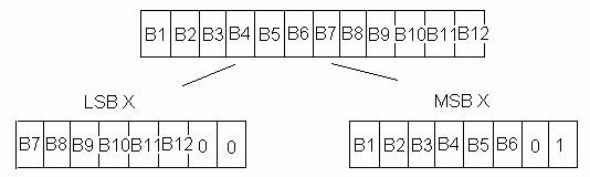
We could then have code in the Processing program to increment through the four states (LSB X, MSB X, LSB Y, MSB Y) and to reject data that deviated from that sequence (and wait to pick the next correct). This way, it was more robust to errors.
With this system in place, we could now test a few things. First, we varied the BAUD rate. We started low, at a BAUD rate of 600:
*This was too slow and laggy, because we could only get about 18 position readings per second (~600 bits/second * 1 byte/ 8 bits * 1 position / 4 bytes ~ 18). This can lead to aliasing if the user oscillates back and forth faster than 9hz by the Sampling Theorem (which is possible). It also just looked bad. So we kept increasing the BAUD rate until we got up to 38400, which seemed to be very good.
At this point, we were ready to test the effect of precision for the X and Y readings. Note that we were drawing to an 800x800 canvas, so technically all we needed was ceil(log2(800)) = 10 bits per reading if we were going to have each possible pixel covered. So we downed the precision from 12 bits to 10 bits and didn’t notice any difference. This meant that we could have added 3 status bits on the end of each byte and splitted the least significant and most significant parts of each reading into 5 bits (and still kept the transfer rate at 2 bytes per position). With three status bits, we could have encoded 3 degrees of freedom, which could be used for extensions of the Etch-A-Sketch in the future.
Keeping the original settings (with 4 bytes per position), we downed the precision to see the effect, and started to notice the quantizing down below 7 bits. There was a huge quantization problem at 4 bits (since there were only 16 possible positions to access in the x and y directions). In the end, we just stuck with 12 bits even though this was slightly better precision than needed.
Part 3: Finalizing the Etch-A-Sketch
There were still a few features missing from the Etch-A-Sketch that we wanted to add. Namely, we wanted the Etch-A-Sketch to clear when an accelerometer on the board exceeded a certain threshold, and we wanted to be able to change between 3 different modes: Cartesian Coordinates (the default X and Y mappings, which we started with), Polar Coordinates (one knob would be mapped to R, and the other to theta), and “Color & Weight Mode” (one knob would be mapped to the grayscale value of the lines being drawn, while the other knob would be mapped to the line thickness). To send these extra parameters, we sent a fifth byte (after the four bytes for position data) in each cycle. The most significant two bits of this byte would tell the mode (00 cartesian, 01 polar, 10 color_weight). We set the third most significant bit to 0 if accelerometer exceeded a certain value (and we wanted to clear the screen).
We had a capacitive sensor of our own invention, which we’ll explain in further detail in the NIME section, that we pressed down on to change the mode. We kept track of the mode on the STAMP and sent it over when ready. And then we simply read the accelerometer every time the STAMP program was ready to send over data, and when it exceeded 300 (by experimentation), we would clear the screen on the Processing side.
As far as the Processing interface goes, we drew the text “Cartesian,” “Polar,” and “Color & Weight” to the screen to let the user know what mode the program was in. If the user was in the “Color & Weight” mode, then we drew a sample line at the bottom of the screen so the user could see what those settings looked like (below the canvas…we added 100 extra pixels to display the mode and this line).
NOTE: The final version of the embedded software can be
found in Sketch_Embedded.bs2
The processing code can be found in etch_processing.pde
Part 4: Beginning the NIME
First, we
decided it would be easier if we could use the build-in midi synthesizers on
our computers instead of hauling everything down to the lab every time to use
the synthesizers there, so we created a program in Processing to invoke one of
the midi synths on our computer (midi_processing.pde). We didn’t have to modify much of the code on
the STAMP; we just had to synchronize the BAUD rates of the stamp with
Processing and output our data to pin 16 like before. And we took advantage of the fact that
Processing was created on top of Java by using Java’s
Once we had the midi program working, we started experimenting with a rather crazy idea we had; we filled a bottle with water, saturated it with salt, stirred it around to mix it up, and placed two wires in it. In this fashion, we created a variable resistor whose resistance would change when we blew into it. The idea was to have this control amplitude or instrument sound. The pitch would be controlled by an antenna, so this would be like a Theremin with a nonconventional amplitude control (blowing to control the amplitude). Unfortunately, neither one of these ideas ended up working very well. The salt solution did change when we blew into it (actually, the resistance went down when we disrupted it, which wasn’t expected), but it was extremely difficult to control, and often took a very long time to settle back down again (clearly unfeasible for an instrument that we want to respond to human interaction in real time). It was just too frustrating, so we abandoned it eventually.
We realized that the salt solution wasn’t a very good idea to control by blowing, but we wondered if perhaps we could control it better if we put a solution of salt in a pan and had two wires in it that we could move back and forth (perhaps to use this to control pitch, like a linear potentiometer except novel since it involved water). We anticipated that a very precise control could be created from this, since resistance is directly proportional to distance (the farther apart the two wires were in the salt solution, the higher the resistance should have been). And when we did this, the resistance did increase (according to our multimeter) when the distance increased. However, the range was terrible (for some reason, it only varied from about 3 k to 3.4 k in one instance at the extremities of the pan). We had a very difficult time justifying why the resistance was still 3k when the wires were so close to each other, and we were very disappointed with this outcome. But we had to move on and try other sensors.
At this point, we were still hoping to get the antenna working for the pitch. We tried a bunch of different objects for this. First, we tried a long, bare wire, but that didn’t have any measurable capacitance until we were practically touching it. Eventually, we modified the idea to include two pieces of cardboard covered with aluminum foil, which we could pull towards and away from each other (sort of like cymbals, but to control pitch). Although we got a slightly better range of capacitances, the best range was still when the boards were only a couple of centimeters apart (very hard to control with them that close together). So we decided to put some cardboard in between the two aluminum boards to prevent them from completely touching, to see how putting pressure on the boards with the cardboard in between would end up. This actually ended up giving us such an amazingly good range, that we used this sensor in our final product (with computer paper taped onto one of the boards). We accidentally created an extremely precise force sensing capacitor (RC time readings from 600 at rest to 6000 when applying most of our body weight, with everything in between). In our final product, we put this on the ground and used it like a pedal to control amplitude
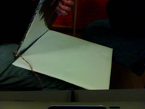
Figure 1: The aluminum/paper Force Sensing
Capacitor “Pedal”
Part 5: Unto this world, a Magical Musical Swiffer is Born:
So we had a good amplitude control, but we were lacking with pitch control now. We were sitting in Chris T’s room wondering what to do, when all of a sudden Chris K spotted a swiffer sitting by the wall. And the rest is history. Actually, we still had some trials to go through before the final product. Our first idea was to attach an accelerometer to the top of the swiffer and map angular displacement to pitch. This approach failed, however, because of problems with noise in the accelerometer and the difficulty of finding a good mapping. All we could really do with this configuration was to generate many, many notes per second that oscillated around a certain pitch (but it was very chaotic). Because of the lack of control, we decided that we needed a better mapping.
At this point, we decided that an accelerometer would not be a good idea for pitch mappings, so we went out to the lab and got an exponential slide potentiometer for pitch (but we didn’t want to abandon the swiffer idea completely…we knew we still wanted to use it somehow to help with the musical expression). The first thing we did was try to linearize the slide potentiometer. We originally did this by figuring out the leftmost bit that was a 1 (like taking log2 of the reading). But because the sensor was not perfect and did not cover the full range from 0 to 4095, we were only able to get 9 notes out of this instead of the 12 that we should have been able to get from a 12-bit word (the potentiometer didn’t go below 10, which eliminated the possibility that the leftmost bit would be any less than 4),. So we ended up having to do something a bit nastier; we carefully measured equal increments of 0.5cm (the full range of the potentiometer was 6cm, so this gave us 12 distinct notes), and we hard-coded the increments into a subroutine getpitch (see Swiffer_embedded.bs2 for more details). This wasn’t the most elegant solution, but it worked extremely well.
By now, we were able to hit up 12 notes pretty cleanly with the slide potentiometer. And we still controlled the amplitude of these notes with the aluminum capacitive sensor we created on the floor like a pedal. But we wanted to use the swiffer in this instrument somehow. We then noticed that the 12 notes we could reach on the slide potentiometer covered an octave. So why not use the swiffer to shift the base note on the potentiometer by an octave? This is exactly what we did; we started the slide potentiometer on a C and had it go up to a Bflat, and we shifted the base octave of the C based on the left-right position of the swiffer:
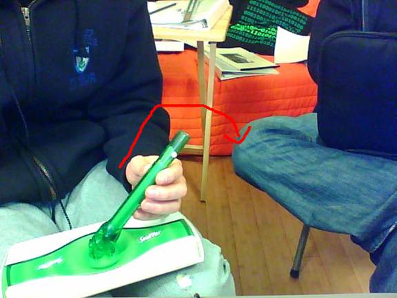
Figure 2: Moving the swiffer w/accelerometer left and right changes octave
Now all of a sudden, we were able to get a bunch of really cool effects with octaves; jerking the handle back and forth quickly cycled through many octaves of the same note at once (something difficult to do on traditional instruments). So our instrument lends itself naturally to pieces with many octaves in them. This also allowed us to reach many more notes (just relying on angular position/gravity leaves at least 8 octaves under stable conditions).
So at this point, we were almost finished, we just a had a few finishing touches to add. When we switched between two notes that weren’t directly adjacent to each other, we also hit up all of the half steps in between. So we created a “button” out of two wires and a resistor (when we pressed our finger over the wires, we completed the circuit with our finger with some finite resistance forming a voltage divider with the resistor in series, changing the value read on port AD1). When the button was pressed, we played notes whenever they changed, but we did nothing when the button was not pressed. This allowed us to change between notes and octaves without the audience hearing every note in between. One final modification we made was to have moving the swiffer forward and backward quickly enough change the instrument sound, just to spice things up a little.
Conclusions, avenues for further research, and some
nostalgia:
In this lab (especially with the NIME), we went through many iterations, and found stuff that worked well and stuff that just sucked (the salt solution, trying to map accelerometer to pitch based on angular position, and expecting jerking not to screw it up). Overall, we were looking for physical mappings that gave the user a good amount of control over parameters of the instrument, but that still allowed for a unique form of musical expression and instrument sounds. Our final product had the following advantages to it:
*It had the potential to play traditional songs with some practice because of the ability to control notes over a few octaves (normally about 4-5), but it also lent itself to new forms of musical expression, especially those that require rapid fluctuation between octaves of a particular note (which I know from experience is hard on the violin)
*It had a certain physicality to it; feeling the position of the swiffer allowed for development of muscle memory that helps to learn the instrument, developing motion with the thumb for changing the pitch.
*Degrees of freedom in convenient places: both arms were occupied (one to control pitch, the other to control octave, playing/instrument sound), and a leg could control amplitude (the pressure sensor was cheap and could be stomped on very hard)
*We put a strip with all of the note names on the potentiometer, which helped to reduce the learning curve
*We even added an earplug to the slide potentiometer to make it comfortable
We were both very satisfied with the evolved instrument, but there are a few things that could still be improved:
*We had some problems with bouncing with the button (and making the button two wires is inherently imperfect, since how wet the finger is affects the threshold that we get when the button is pressed)
*We also had a problem with boundaries; that is, if the slide potentiometer was right between two notes, it would start oscillating between the two because of noise (so it was better to hit the notes in the center). We also had this problem with the swiffer if we were close to the boundary between two octaves (it would oscillate between two octaves). Perhaps some sort of lowpass filter of the octave data could have been applied
We were very sad to part with our instrument. We hope to reconstruct it sometime, improve it, and perhaps perfect playing techniques. Chris T only had about an hour to practice, but with regular practicing perhaps this could become a new instrument in an orchestral ensemble!