Duke Dusty 2 & Roomba Research on
ROS Platform, Summer 2010 Logbook
Chris Tralie
Adviser: Matt Reynolds
Tuesday 6/22/2010:
Note to self: Don’t forget to unplug the Hokuyo when charging the base
station; otherwise the hokuyo will drain more power than is coming in through
the AC adapter and the thing will be dead by the time I get to it.
I accidentally deleted my logbook that I had started earlier this week when I reformatted my computer last night. To make up for it, let me summarize a few key findings I’ve made over the past couple of weeks, along with my goals for the summer:
Goals:
1) Primary Research Goal: Port the functionality of the EL-E platform over to Dusty 2 here at Duke, with the idea that semi-autonomous control can be combined with low bandwidth input from users with disabilities on a cheap, affordable platform. Get navigation up and running and experiment with arm
NOTE: The arm will need to be constructed at Georgia Tech
2) Secondary Research Goal: Do experiments with high-band antenna to see how well I can predict the locations of objects; this is important because I need to get as close as possible to the objects before the low-band antenna can be used.
*My initial idea for this is to try to collect as many localized RSSI readings as possible for a tag and to use RANSAC and triangulation to predict the tag’s location (since I’m expecting a good number of outliers from multipath)
3) Side Project; Explore arm in the lab
Key findings so far:
I’m using the irobot_creat_rustic library to control the roomba. Here is the topic interaction setup I have so far:
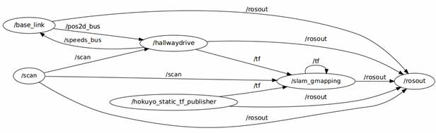
Figure 1: The topic interactions doing map building while autonomously navigating the hallway. The most important parameters for slam_gmapping are the tf transforms that take the odometer to the base of the laser (odom -> base_link) and the LaserScan message from the /scan topic published by the Hokuyo. Note also that
I can also manually override the hallwaydrive program’s commands if I set the parameter /hallwaydrive/automatic to 0. This allows me to use a GUI program to drive the robot myself. Here’s what the topic interaction graph looks like in that case:
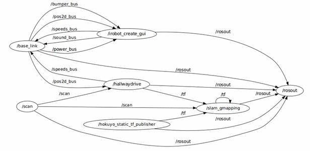
Figure 2: Map building with the potential to override using the "irobot_create_gui" node provided in the
I figured out how to look at the map-bulidng online. All that needs to be done is to execute “rosrun nav_view nav_view”. I found this out from the tutorial:
http://www.ros.org/wiki/slam_gmapping/Tutorials/MappingFromLoggedData
But this can be done online in spite of what the tutorial says.
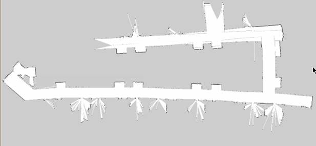
Here’s an example of a map that I have generated using the software:
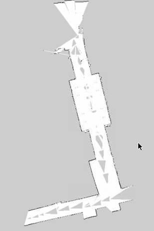
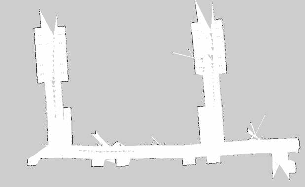
Figure 3: An example occupancy grid built in part of the hallway. The odometric drift doesn't actually seem too bad, but for some reason there are holes in the middle and I can't figure out why.
**I’ll have to come back later and figure out why those holes are there
in the middle of the occupancy grid…
5:14 PM:
I shifted my hours today so I could come and work late to get a decent map of the hallway after people left (I’ll be here until about 10 PM). There are a few things I need to fix before I can do that, though. The first thing I’m working on is making my local hallway navigation program better. I’m going to make it try to avoid obstacles that are a certain distance away, in addition to making it try to stay in the center of the hallway. I’ll have it turn away from a close obstacle when it’s within a certain distance, or if there isn’t an obstacle within a specified distance, I’ll do the centroid thing I did last year. Here are a few measurements (some of which I actually need for the navigation stack).
The roomba radius is about 21cm
So I’ll have the close obstacle cutoff at about 0.5 meters and experiment with that.
6:54 PM
After some tweaking I finally got the near obstacle avoidance plus centroid finder to work. There was a bug that took me a while to find where for some reason, some of the laser scan bins turned out to be zero. This was really screwing up what it thought to be the closest obstacle, and it was also causing divide by zero errors (since the sharpness of the turn is made to be inversely proportional to the distance). But now it works so well that it actually avoids all of the chairs in this lab and it’s able to get itself out of that. I just need to get the manual override working and then I’ll be ready to get some real data out in the hallway
8:30 PM
I’ve been building some maps but running into problems. The maps have holes in the center that sometimes really screw them up; the robot gets stuck in one of the holes and this makes the hallway artificially short, etc. Also, the loop on the 3rd floor CIEMAS is abysmal just like it was last year in that area where there’s tons of glass and the laser scanner misses it, and it tends to curve off there, making it impossible to close. I’m going to have to drive the robot really straight and really slowly in that area if it’s going to work. I’m going to add the feature to have it drive straight in the hallwaydrive program if I change a ROS parameter quickly on the fly.
Wednesday 6/23/2010
I figured out why the map was getting holes, thanks to Travis Deyle. Here’s an e-mail exchange I just had with him:
Okay
great, thanks, that's a relief. I suppose trying to view the map at the
same time it's building on that dinky little netbook wasn't the best
idea. It definitely did look like the processor was maxing out.
I'll make a bag file and compare the results. I'll also make sure to do
multiple loops. Or if this continues to be a problem, I'll just make a
filter that gets rid of the gray stuff.
Thanks,
Chris
Travis Deyle wrote:
The holes are likely due to
the online mapping not incorporating all the data (processor-limited).
This could be handled using bag files to build offline maps instead.
Actually, this shouldn't affect your map in the slightest. After you save
your map, only the black locations (which you can reinforce by editing the
resulting map image) are used for localization. The gray is
"unseen" and you can manually remove it from your maps. Beyond
that, your only recourse is to slow the robot down (more scans), make multiple
passes (which you should do for loop closure anyway), and / or do the
map-building offline.
~Travis
On Wed, Jun 23, 2010 at 12:05 AM, Chris Tralie <ctralie@princeton.edu <mailto:ctralie@princeton.edu>> wrote:
Hi Travis,
I've gotten SLAM to work online, but I
can't figure out why I'm
getting holes in my map. I have attached an example
map that I've
built to this e-mail. Any ideas why there are holes in
the center
along the path of the robot? This sometimes really
screws things
up as the map is being built as well. The laser is not
obstructed
up there, and I can't really think of another explanation
for it.
Thanks,
Chris.
12:20
PM
Here’s another e-mail exchange I just had with Travis:
AMCL
takes in odom and laser. It updates a transformation from map (parent) to
odom (child) -- you should not specify this transformation. Look at tf
view_frames after you get things running.
For
navigation, you should just use the base_link expressed in the odom frame.
~Travis
On Wed, Jun 23, 2010 at
12:12 PM, Chris Tralie <ctralie@princeton.edu> wrote:
Hi
Travis,
When I'm setting up the navigation stack, I'm getting odometry
information from the roomba at the same time that AMCL is giving it's own
version of "odom." But it looks like AMCL only uses laser
information? So should I just ignore the roomba's version of odom and use
AMCL's during navigation? Is it the case that the roomba's odom is only
important during map building and I can ignore it during navigation?
Also, I'm planning to do an identity transform between /odom and /map, is
this correct?
Thanks,
Chris
I’m still a bit confused about the tf
transforms here; is odom being updated by amcl but then overwritten by my
published odom? I guess I’ll have to see
what happens and maybe e-mail Travis again.
But first I’ll look at tf view_frames and post what that looks like
here.
Found a really good video tutorial on how to set up global path
planning targets in RVIZ
http://www.ros.org/wiki/navigation/Tutorials/Using%20rviz%20with%20the%20Navigation%20Stack
Don’t forget to save RVIZ parameters after
running this tutorial!
3:00 Meeting with Matt
Keep an eye on the odometry and whether it’s straight; does it have to
do with battery?
Tweak the parameters listed on the
gmapping site
http://www.ros.org/wiki/gmapping
especially the parameters: linearUpdate, angularUpdate,
temporalUpdate(?)
Task 1: Assess the tradeoffs between making linearUpdate smaller or larger; is
the time complexity of the linear algorithm such that it goes faster if more
updates are done over a smaller length interval? Will that make it more or less accurate?
Task 2: Set up the RFID reader with Travis’s driver, make sure that the
odometry doesn’t get messed up by the placement of the reader (it seems to be
very straight lately and I don’t want that to be compromised)
Research Idea Set 1
·
(Matt’s
ideas on high-band RFID localization)
·
Try to maximize RSSI
·
Look
up Travis’s paper “Foviated RFID […]” find on IEEE explorer
·
Only
update the goal periodically since RFID data is noisy
·
Talk
to Travis about some of the algorithms he’s been thinking of
·
“Rumors
of my death have been greatly exaggerated”
Thursday 6/24/2010
I just created a program that allows me to steer the robot manually
with the keyboard and I noticed something interesting that I should have
realized before….a positive “angle” turns the robot to the left
(counter-clockwise), while a negative angle turns it to the right
(clockwise). I suppose I thought
“positive=right” before for some reason, but I guess this makes more
sense.
I’m also going to have to keep my eye on the laser scans, because they
appear to be backwards in RVIZ
2:00 Skype Session with Travis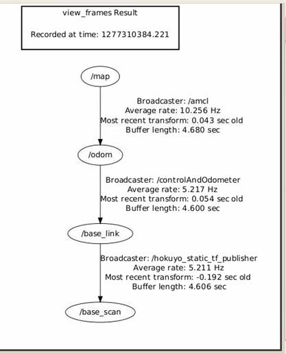
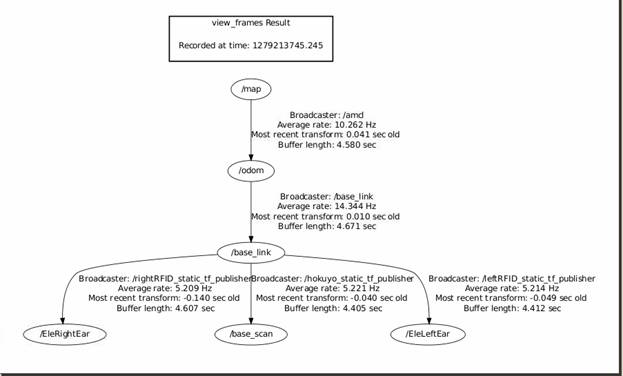
Figure 4: A transform tree showing what happens during
navigation. As Travis explained it to
me, AMCL publishes a transform between map, which is a fixed frame, and odom to
correct for odometric drift (this transform is not static). So by the end the transform from map to
base_link and base_scan has the best corrected position and orientation.
Problem for finding tags with highband: Tags were at different height
Travis’s ideas for research: Take antennas and use ROS to set up
waypoints; take as many readings as you can.
If I have 50 tags in this room, how many can I realistically expect to
read. How far away do I have to be?
Servoing works, but we have no idea how well it works in a home
Research Idea Set 2
PUBLISHING!!! ICRA: Due date
September 15th
1) Get the create platform to the spot that
EL-E was
2) Take the platform into an actual house and
get “real-world” data; how many tags can I actually expect to read
3) Working on estimating the position of the
tags with the particle filter; get localized tag readings and use that to get
close enough so that there’s not as much multipath
Particle filter could works as a node
NOTE: TF interpolates, so
all I have to do is save my bag file and use that when I want to figure out
where a reading was taken
TODO over next couple of days:
*Do Probabilistic Robotics
reading
*Look at RFID papers on healthcare robotics site
http://www.hsi.gatech.edu/hrl/project_rfid.shtml
***Do TF interpolation test and send
Travis the results***
Now I’m going to do some more tests with map building. I’ve driven the robot around in a loop with a
program that I made to manually drive it; it appears to go in straight lines
now pretty well so I’m not going to bother using my centroid-finding program
anymore since it gets so screwed up in the center of the glass walkway
anyway. I’m going to play back the data
in a bag file and attempt to generate a map varying several parameters of the
map-builiding, such as linearUpdate and angularUpdate (probably the most
relevant parameter will be linearUpdate).
The first test will be done using default values:
One thing I noticed during the tests was that the robot hardly drifted
at all, which I said before was the reason I now manually drive it instead of
having my centroid-finder program correct automatically on the fly. I had it going at a very slow speed most of
the time (0.07m/sec ~ 0.157 mi/hour) and I’m wondering if this had something to
do with it. I’m going to keep my eye on
it once I attach the RFID reader and hopefully it remains good.
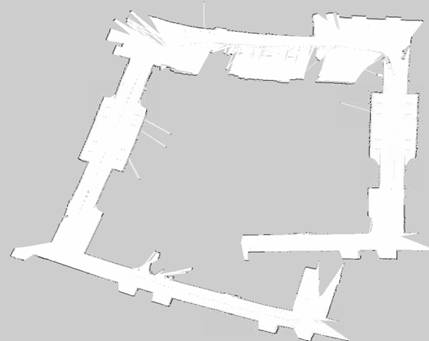
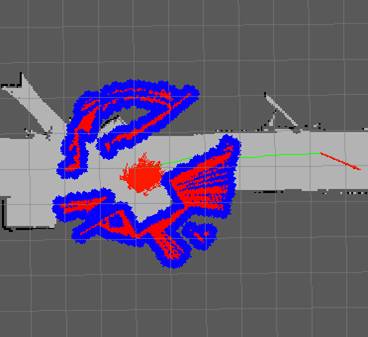
Test 1: linearUpdate = 1m, gridResolution = 5cmx5cm per block
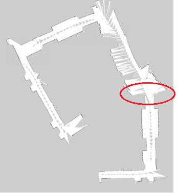
I have highlighted a trouble spot.
I do want to point out a few positives, though. For the most part, the hallway corners do
form right angles, and there is significantly less drift than there was last
year. But there was one corner that
completely hosed up all of the results, and I believe it’s because of all of
the glass that’s there (also, the robot
got stuck on something while I was trying to move it on the circled red spot). I’m going to do a few more tests with
different parameters, but I think this might be an inherent problem with the
data set. So I may either need to
eliminate that segment of the data set or redo my testing with a different
initial position of the robot.
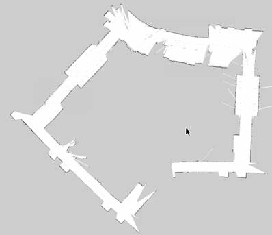
Test 2: linearUpdate = 0.5m, gridResolution=5cmx5cm per block
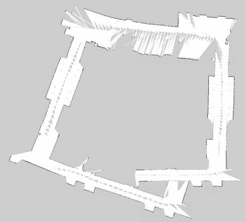
The results were actually much better this time! In the documentation it says that the
parameter “linearUpdate” decides how to “process a scan each time the robot
translates this far.” So I suspect it
was throwing out a lot of laser scans which definitely would have caused
problems in a particularly huge variation section like the turn I circled
before. One thing I noticed this time
around is that the processor was just about maxing out; it just finished one
update right as the next one started.
I’m going to try halving that parameter again, but I may need to run
this test on a better computer (i.e. mine own personal laptop) in order for
that to work and not hiccough. Here I
go…
Test 3: linearUpdate = 0.25m, gridResolution=5cmx5cm per block
I’m noticing here that it can’t quite keep up with my request to have
it update every 0.25 meters at all times.
I’m going to try to move it onto my computer next and see if that helps. Actually, before I do that, I’m going to change
the “publishing rate” of the rosbag client and see if that helps at all. I’ll make the publishing rate half and see if
it’s able to keep up better. The only
obvious drawback here is that I’m going to have to wait much longer for the
tests to complete…
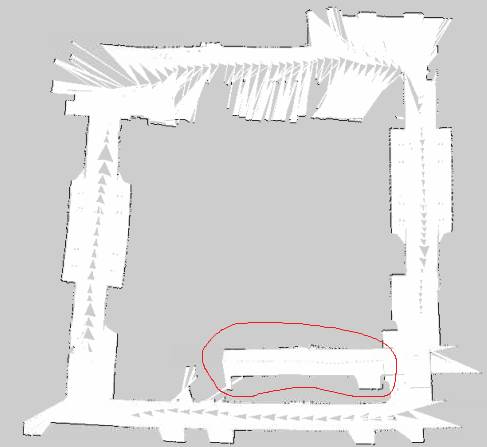
Wow! For the first time ever
I’ve gotten loop closure! Now there is
an obvious artifact where for some reason the left side of the map was longer
than the right side of the map, so when it merged them back together there were
some issues. I’m going to try running
this on a faster computer and see if that fixes it. If not, there’s a possibility I may need to
make a new dataset since it could be due either to odometry drifting or to the
time my robot got stuck.
Test 4: linearUpdate = 0.25m, gridResolution=5cmx5cm per block (but
this time I slowed down the playback to a quarter of the rate it originally
was)
I’m cutting the test short because the results look so significantly
better. I’m going to make the playback a
tenth of what it is and move linearUpdate down to 0.1m for my next test. This is going to take a while so hopefully
it’s worth it.
Test 5: linearUpdate = 0.1m, gridResolution=5cmx5cm per block (slowed
down playback to 0.1x speed)
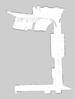
Test 6: linearUpdate = 0.05m, gridResolution=5cmx5cm per block (slowed
down playback to 0.05x speed)
This test took over 10 hours on the netbook…
Now I’m noticing somewhat of an adverse effect of increasing
linearUpdate. It actually seems to rely
a bit too much on odometry, as seen by the drift up top. I’m going to go back to a linearUpdate of 0.25m since that’s the only case where
I got loop closure, and start varying some of the other parameters there to see
if I can get even better results. At
some point, I’ll also probably have to touch it up by hand.
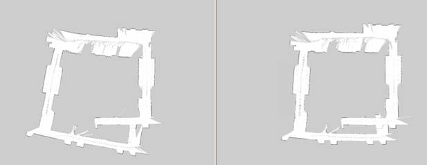
Test 7: linearUpdate = 0.25m, slowed down to 0.4x speed, tested with 5
iterations of scan matching (left) versus 10 iterations of scan matching
(right)
Friday 6/25/2010
I attached the RFID reader to the Hokuyo today, being careful to center it as much as possible. I even used industrial velcrow to hold it in place. I drove the robot straight and it did not appear to drift, so it looks good so far.
Here’s an e-mail I sent to Travis. He asked me to do some tests on how TF does interpolation, and I’m trying to get his RFID driver up and running.
Hi
Travis,
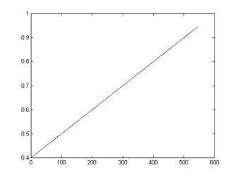
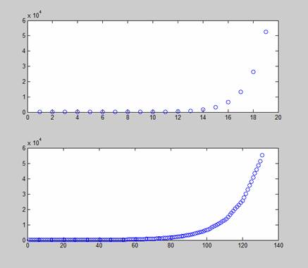
As promised, I did some tests with TF interpolation.
My first test had just a linear increase of one coordinate of my translation
vector, updated at 1hz and resampled at 100hz. This was linearly
interpolated as expected. My second test had an exponential increase
(doubling), published at 1hz and resampled at 10hz, which also appeared to
linearly interpolate. I attached my datasets to this e-mail as well as a
few plots in matlab to show what I'm talking about. It's especially clear
by the exponential plot around the "bend" that linear interpolation
is taking place.
One caveat is that I looked back 5 seconds in time when I ran my tests; I was
having trouble getting TF to interpolate at the current time. But this
certainly wouldn't be an issue for offline data; but I'll have to look more
into doing this online.
My next question for you is how do I launch your RFID driver? I don't
know Python (yet), and it doesn't appear to be a node as I expected (i.e.
rosrun hrl_rfid doesn't autocomplete). Once I have it running I intend to
subscribe to the RFIDread message.
Thanks,
Chris
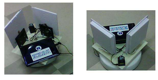
Here are the pictures I attached to my e-mail:
Now I’m working on getting the RFID driver up and getting navigation
working simultaneously. My map isn’t
perfect but I’ll attend to that later; the one where I got basic closure
(linearUpdate=0.25) is good enough to start with. Also, Travis is helping me with the RFID
driver.
Tuesday 6/29/2010
I was too lazy to
make an entry yesterday so here’s my entry for today: I got Travis’s RFID
driver up and running and I tested it with a few tags using rostopic echo, but I have been having a
little trouble getting the C++ interface working to call the service
(/rfid/mode [‘query’]); which means I have to do it the console for now (same
thing with the actual RFIDread msg that’s published to the topic).
While I’m stuck on that, I went ahead and made another .bag file of
the hallway, this time cutting out the section that was giving me trouble
before (because I don’t need it for testing anyway). I ran the data back at 0.4x speed and did a
linearUpdate every 0.25 seconds, and here are the results I got:
Now I’m going to try to get navigation up and running; I was also
having trouble with this yesterday (it wasn’t able to find a path for some
reason but I suspect it may have had something to do with the occupancy grid (I
was using the previous one which had the phantom section of the hallway
sticking out once the loop was closed).
And just to be sure, I’m going to touch up the occupancy grid here and
erase the little gray spots
Starting to run navigation tests, looks like the laser scans may be
backwards (but I am at least getting path planning working now)
Aaaah no wonder, I had my quaternion wrong! I accidentally had it as a 180 degree
rotation about the x-axis (my quaternion was (qx, qy, qz, qw) = (1, 0, 0,
0) instead of (0, 0, 0, 1) for identity)
Doing some more testing with the navigator; it looks like the
rotational commands may need to be converted from radians per second to
mm/sec. ROS gives them in radians/sec,
but I need to look at the create’s open interface to see what it’s
expecting. It seems to me like the
rotation is going too quickly at the moment.
In the create’s open interface there’s only commands for controlling
the different wheel speeds. The driver
has some level of abstraction above that which I’m not sure about. So I’m going to try to reverse engineer the
controller using a stopwatch. I put it
to a rotational speed of 0.08 and counted 21.233 seconds for a full revolution.
Need to convert from units/sec
to radians/sec
(2*pi / 21.233
radians/sec) / (0.08 units / sec) ~ 3.7 (radian/sec) / (units/sec)
Now let me verify that the speed is on a scale from 0m/s to 0.5m/s mapped
to the range [0, 1.0]
Took 50 seconds to travel 8 feet at a speed of 0.06
(8 feet/ 50 sec) * (12 inches / foot) * (3.54cm /inch) = 6.8 cm / sec
0.06*50cm/s = 3.0 cm/sec
I’m surprised to find that the create went
more than twice the speed I expected it to go.
Is its max speed more than 50cm/sec?
More testing is needed. But first
I will try the new conversion factor for the angular velocity
It still seems to think it’s turning faster than it actually is, which
is what I think is causing these artifacts of the laser scan:
I’m going to redo the measurements and do some more tests for the
turning rate conversions (I’m thinking to myself that I might need to
re-calibrate these constants every time I add something to the base)
Tuesday 7/6/2010
It’s been a while
since I’ve done an update; I’ve mostly been doing reading on Bayes, Kalman, and
particle filters. I’ve also been stuck
on the navigation control still (and I’ve been off since Thursday, today is my
first day back). Here’s part of an
e-mail I sent to Travis about the navigation control problem:
I've
also been having an issue with the navigation stack that maybe you could have
some insights on; it loads properly but there seems to be some discrepancy
between the drive commands that are being sent on "cmd_vel" and the
commands that the roomba accepts; cmd_vel gets Twist messages published to it,
while my roomba driver accepts this "Speeds" command with
"forward" and "rotate" as its fields:
http://www.ros.org/doc/api/irobot_create_rustic/html/msg/Speeds.html
I tried doing timing measurements to get a mapping from "rotate"
units to radians per second, but it varies based on whether forward is nonzero
(or small) or not, because if the robot is barely moving forward both wheels
oppose each other, but if it is moving forward and turning both wheels are
going forward, but one is faster than the other; so the turn rates are
different for the same "rotate" field if the speeds are different.
Anyway, what I've noticed as a result is that the robot fumbles around a lot
for a frustratingly long time before it gets to its destination.
I tried timing it to figure out if I could come up with a mapping
between the commands between cmd_vel and Roomba’s “Speeds” command, but I
couldn’t get it to work. Here are a few
excel plots I made in the process
|
"Rotate" |
Time 1
Revolution |
Radians / sec |
|
|
0.1 |
15.8 |
0.063291 |
0.39767 |
|
0.2 |
8.429 |
0.118638 |
0.745425 |
|
0.3 |
5.461 |
0.183117 |
1.150556 |
|
0.4 |
4.115 |
0.243013 |
1.526898 |
|
0.5 |
3.276 |
0.30525 |
1.917944 |
|
1 |
1.780286 |
0.561708 |
3.529313 |
So the conversion appeared to be 3.4849
radians/sec for every “unit” in the
roomba’s Speeds “rotate” field. But this
only works if it’s stationary.
I also did a similar thing for the “forward” part of the Speeds field
in isolation and got the following table
|
"Forward" |
Time to travel
2.44m |
velocity |
Conversion
Factor |
|
0.1 |
26.504 |
0.092062 |
0.920616 |
|
0.2 |
12.458 |
0.195858 |
0.97929 |
|
0.3 |
8.629 |
0.282767 |
0.942558 |
|
0.4 |
6.268 |
0.389279 |
0.973197 |
|
0.25 |
10.92 |
0.223443 |
0.893773 |
But I’ve decided now it’s not worth using the rustic driver; I’m
instead going to go back and use the irobot_create_2_1
driver because it allows me to specify commands exactly in mm/sec, and it also
has a command that drives the robot in a circle.
If I want a certain linear velocity, v, and a certain angular velocity, omega, all I have to do is specify that the robot travels around a
circle at speed v which has a radius
v/(2*pi*omega). If omega is below (0.01), then I will simply
tell the robot to drive forward at speed v.
Now I have to go code this up…
Looking at the IRobot Create open interface documentation, I noticed
that the variable angle in sensorPacket stores how many degrees
the robot has rotated in either direction since the beginning. It’s a signed int, so it overflows at 32767
(it actually saturates and does nothing).
This means that I’m okay as long as I don’t do more than 91 revoultions (I won’t worry about
this for now). Distance stores the
distance traveled in millimeters (also an int) since the last time it was
requested.
I just realized that somehow this irobot_create_2_1 driver already accepts cmd_vel commands.
Wednesday 7/7/2010
I went to look at driver.py in the irobot_create_2_1 src directory when I noticed that not only does it already subscribe to cmd_vel and take care of that on its own, but it also publishes its own odometry information and the tf transform from /odom to /base_link. I was running into a lot of problems doing my own odometry and I think that was really screwing up navigation, so now I can ditch the entire controlAndOdometer.cpp file.
I got navigation working!! After switching to this new driver and letting it take care of odometry and cmd_vel commands, I noticed that the create was still fumbling around a lot very slowly and getting confused. So I decided to go back to the default parameter limits for the local navigation since I knew now that the robot would do what they said (since the new driver subscribes to cmd_vel and is able to correctly actuate those commands). Here are the parameters I’m using now:
TrajectoryPlannerROS:
max_vel_x: 0.45 (m/s)
min_vel_x: 0.1 (m/s)
max_rotational_vel: 1.0 (radians/sec)
min_in_place_rotational_vel: 0.4
(radians/sec)
acc_lim_th: 3.2 (radians/sec2)
acc_lim_x: 2.5 (m/s2)
acc_lim_y: 2.5 (m/s2)
holonomic_robot: true
Now all I need to do is get rid of that annoying song the robot plays every time this driver starts! But actually, my next step now will be to get the RFID driver up and running programmatically
Meeting with Matt
45 or 90 degrees
RFID + SLAM Dieter Fox Wolfram (ICCRA 2004 or 2006); referenced in the other papers
*Get another antenna (extra port on RFID reader)
-Create - $229
Netbook - $200-$300
Hokuyo - $2k
RFID Reader - $200
RFID Antennas - $20
TODO: Get two antennas on, try out other hokuyo
Josh Smith – Intel personal robotics effort
Youtube – Natal camera (3D camera), CIEMAS camera
Have lunch with Mac Mason
***Ramesh Raskar
Goals
for the week:
·
Get Travis’s RFID reader up
programmatically
·
Put two antennae on in V shape and
rebuild roomba
·
Try out new Hokuyo
· Get video of navigation in action
·
Read papers: RIFD + SLAM Dieter Fox and
Matt/Travis’s RFID paper
·
Backup code to repository
· Try navigating to a place off of the map
Today before demo:
·
Get RFID reader up
·
Build new occupancy grid
I’ve been playing around some more with Travis’s RFID reader. Annoyingly enough, I can’t do
#include <hrl_rfid/RFIDread.h>
Even though I put “hrl_rfid” into manifest.xml, it doesn’t resolve the path to that header file. Instead I have to do “/home/createbrain/ros/ros/hrl/hrl_rfid/msg/cpp/hrl_rfid/RFIDread.h”. Hopefully I can fix this eventually.
RFID tags IDs are 96 bits long. It appears that in the RFIDread message, the tagID field stores each ID as a 16-byte string, so that it’s completely packed. This contrasts with the Player driver from last year, which I seem to remember having stored the IDs as hex “strings” where each character was a letter or number for each hex character (so the strings were 24 bytes long).
Thursday 7/8/2010
I’ve punched all of the proper holes into the new robot base so that everything can fit, and I’ve done a few measurements on where everything ended up:
Center of laser is 16.5cm in front of center of robot
Camera will be 14cm in front
Here’s a diagram of where I placed the center of the right RFID reader:
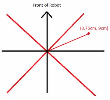
The black axes are aligned with the front of the robot, but I measured the position with respect to the red axes, which are offset by 45 degrees. I need to specify the transformation with respect to the original coordinate system, though. This requires doing a -45 degree rotation from the red coordinate system. In black coordinates, this is:
3.75cm * (sqrt(2)/2, -sqrt(2)/2) + 9cm*(sqrt(2)/2, sqrt(2)/2) = (12.75sqrt(2)/2, 5.25sqrt(2)/2)
~ (9.02cm, 3.71cm)
This means that the other antenna is at position (-9.02cm,
3.71cm)
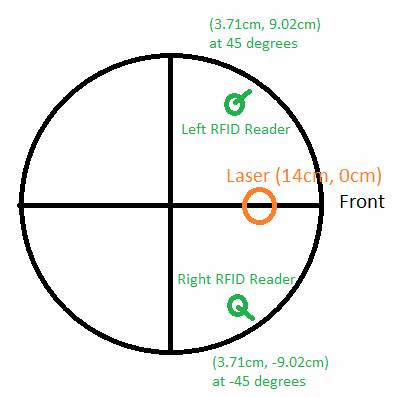
But actually TF specifies the transformations with x towards the front of the robot (http://www.ros.org/wiki/navigation/Tutorials/RobotSetup/TF) so I have to change this again by rotating everything by -90 degrees, making the first antenna (3.71cm, -9.02cm) and the second antenna at position (3.71cm, 9.02cm).
The orientation of the first antenna is at –pi/4 radians, while the other one is at pi/4 radians. Here is a pictorial summary of everything I just explained:
· Quaternion for -PI/4 radians about z-axis: (qx, qy, qz, qw) = cos(angle/2) + sin(angle/2)*urot = (0, 0, -3.827, 0.9239)
Static transform from
base_link to laser: (x y z qx qy qz
qw) = (0.14, 0, 0, 0, 0, 0, 1)
Static transform from
base_link to right RFID reader: (x y z qx qy qz qw) = (0.0371, -0.0902, 0, 0,
0, -0.3827, 0.9239)
Static transform from
base_link to left RFID reader: (x y z qx
qy qz qw) = (0.0371, 0.0902, 0, 0, 0, 0.3827, 0.9239)
After I code up these static transforms I should look in RVIZ to make sure they look right
Monday 7/12/2010
**NOTE: Something I should have noted a long time ago; running RVIZ through VNC is tricky because it requires GL extensions. This means that it can’t be run through one of the :1, :2, :3, etc. TightVNC virtual desktops; it has to be run on the actual desktop that’s being displayed on the screen (Ubuntu’s primary remote desktop server)
Goals
for the week:
· Get video of navigation in action
·
Try navigating to a place off of the map
·
Try map building with new Hokuyo
·
Make static TF transforms for RFID reader
·
Verify the static TF transforms in RVIZ
·
Figure out which antennas are which
·
Do preliminary servoing tests rotating
the robot 360 degrees and plotting the RSSI versus bearing
·
Get servoing working
·
Begin working on RVIZ visualization tools
for RFID tags (particle clouds + external GUI control program for tags)
·
Create a basic explorer program using the
navstack (navigate to random open points in a coarser version of the occupancy
grid)
Not doing after all this week:
· Begin particle filter implementation
· Figure out how to find the closest navigable position to a point on an occupancy grid
2:22PM Update: The
robot is working!!
Here’s an e-mail transaction I just had with Matt:
Looks great, Chris! Sorry about the long delay in remembering where the Hokuyo was stashed. One question: How well does map building seem to work with the new Hokuyo vs the old one? Supposedly the new one has somewhat reduced range and angular resolution (it's cheaper)? I expect that odometry will be pretty much the same (i.e. kinda crappy) unless we get lucky on center of mass of the new platform? Look forward to seeing the servoing and RFID-enhanced map building coming to life. Regards,Matt On Jul 12, 2010, at 2:30 PM, Chris Tralie wrote: The new robot platform has been finished; everything and working, including the new Hokuyo URG-04LX-UG01. I just took it for a spin through the hallway and it's working extremely well with the navigation stack, and the odometry appears no less stable than before. I hope to start working on servoing today, and hopefully be underway with the particle filter collaborating with Travis by the end of the week.
-Chris
<newrobot.png>
I did notice the angular resolution was a bit less when I looked at this in RVIZ. I should try to get exact numbers on this. This didn’t seem to affect navigation at all (I ran a couple of tests and the particle filter was able to track the position pretty well, and eventually correct itself when it was off). I will try to make a new map though.Another interesting thing Matt mentioned was RFID-enhance map-building. This reminds me that I need to make some visualization tools for RVIZ for the RFID tags. Maybe I’ll have a particle filter visualization tool similar to the one that’s being used for odometry.
Got the numbers; there are 454 bins apparently on this new scanner between -80 and 80 degrees. Looking back at what I had running in Player last summer, it looks like I only sampled 180 bins. So this is better than that, but I didn’t get a chance to look at how many bins there actually were in the other Hokuyo.
The official specifications says that the Hokuyo R325-URG-04LX-UG01 (the new one) and the R283-HOKUYO-LASER1 both have an angular increment of 0.36 degrees, though, so I’m not sure (this increment matches with what ROS told me).
Bottom line I’m not sure how important the exact numbers are but I will test it out.
Here’s a screenshot I took in RVIZ of the transforms
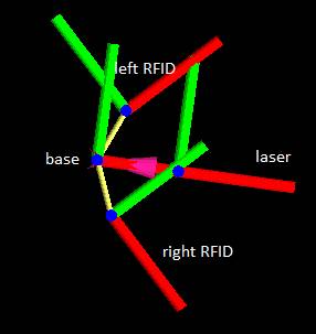
It looks like red is +x and green is +y. This looks correct to me
Just thinking to myself as I’m running a new mapping test; I’m expecting this laser to work just as well as the last one because these hallways are so narrow; even though the maximum range is smaller that shouldn’t matter so much here except around open space
Another thing that I’m thinking of now; I’m reading Travis’s paper on the “foveated RFID reader” and looking at the section that talks about servoing, is that I should do a test where I place an RFID tag in front of the robot and turn the robot 360 degrees around, recording the RSSI value over the 360 degree interval and then plotting this value for both antennas. What I should expect is a symmetric graph with the middle being a global max of the RSSI corresponding to the antenna bearing of zero degrees with respect to the tag. As such, I would expect the two graphs for the two antennas to be horizontal translations of each other. So I’ll run this test ASAP and then think of how to implement servoing based on the results
If anything, my robot appears to be drifting to the right slightly as I’m building this new map…
Some ideas for navigating towards a specified tag (thoughts while I’m still collecting data):
· If tag is not in view at all, navigate along the original path that the robot took to build the map; that is, sample the positions of the robot along the map-building path and create waypoints that cover most of the path
· Recalculate the goal every time the variance decreases below some threshold
· Navigate towards the nearest open spot of the estimated pose is not within the occupancy grid?
Tuesday 7/13/2010
After collecting data, I slowed things down by 10x and constructed the new map overnight using a linearUpdate of 0.25 and a grid resolution of 5cmx5cm as before
The results are slightly disappointing but I think it’s because I did it over such a large area, so it wasn’t really a controlled test.
I’m working on getting the RFID reader all configured now. I have the antennas plugged in such that the left antenna is called “EleLeftEar” in Travis’s driver, and the right antenna is called “EleRightEar.” I’m using the “Venture Research Inc” RFID antenna strength indicator to make sure the driver is working. I noticed that when both antennas are being queried at the same time, the thing only blinks about half as fast on the strength indicator, which makes sense if it’s switching back and forth between which antenna it’s querying.
I was wondering before why the RFID driver wouldn’t go into query mode even though I made a service call from my C++ client. I used to have to start the query manually from the console. But after some more testing I realized that it doesn’t work putting it into query mode until after the driver has initialized and is “waiting for instructions.” I’m going to have to figure out a way to detect when it’s gotten to this phase and to avoid making the service call before then.
Skyping with
Travis:
Base_Local_Planner
Data-Driven Model: 3D histogram (range, bearing, RSSI)
Make a more general histogram for roomba??
*Look for explore behavior in the navstack (explore)
*Look into using NavView?
*Marker for ground truth; external GUI for particles
Modified Research Ideas:
*Environments to test in: Capture a dataset in my apartment
*Make sensor models??
Main Goal: Set up good, realistic ground truth data sets and gather RFID reads by “exploring” around: lab, apartment, hallway
Set up tags: different heights, get a pseudo-3D model
Do evaluation on realistic settings
1. Get visualization working
2. Think about how to build the model, how to test the model, and how to capture the ground truth everywhere
Archive.org if publishing date not met?
Wednesday 7/14/2010
Travis wants me to work on visualization tools so that’s what I’m going to be doing for the next day or two. It’s going to be all coding; I decided to try to publish to things that RVIZ can render and to create an external GUI with wxWidgets for deciding which heatmap to display, etc. So probably not too many updates here, I’m just going to be hammering through C++ code
(!!!) I finally resolved the linking problem I was having with the hrl_rfid library!! Here’s an e-mail I sent to Travis about it:
Hi Travis,
I finally got the hrl_rfid package to link to my C++ client
node programs by specifying a relative path instead of an absolute path to the
header files (which is obviously vital if this is going to be at all usable by
other people). As it turns out, you need to add an <export> tag to
the manifest.xml file in your hrl_rfid driver as follows for dynamic linking:
<export>
<cpp cflags="-I${prefix}/msg/cpp -I${prefix}/srv/cpp"/>
</export>
I've attached the updated manifest.xml to this e-mail, could you commit that to
the hrl_rfid repository? This way we'll have a consistent copy and I can
continue development of my visualization tools.
Thanks,
Chris
So now I can be confident that my code is portable at least.
Thurdsay 7/15/2010
Just been working a lot remotely on the code for the RVIZ RFID displays. Lots of little programming hurdles and looking up stuff in the documentation, but nothing really worth writing here…
Came into the lab today to get some test data for my RVIZ visualization program. I noticed that the callback function for an RFID read triggers constantly if I’m in query mode but with an RSSI strength of -1 when no other tags are there. I realized this must be from the two antennas seeing each other, so I ignore the callback if the rssi is -1.
I’ve been having a lot of trouble with the TF transforms in my heatmap viewer but I just realized I’m playing back a bagfile and I forgot to do
rosparam set use_sim_time true
*forhead smack*
Tuesday 7/20/2010
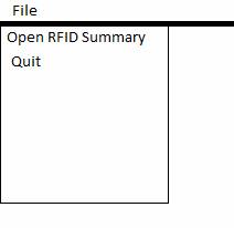
Still been having lots of issues with TF, I think I’m going to have to contact Travis about this. Anyway in the mean time I’ve begun working on the GUI to control what point cloud data to display using wxWidgets. Let me just make a few notes here on some plans
· Use the wxFileDialog to have the user choose a file to open with RFID entries as an alternative to running the program “live” with RFID reads and TF data coming through. This dialog can also be used to begin running a bag file(?) and choosing where to save a summary file from that bag file
Here’s my pictorial concept of what I want:
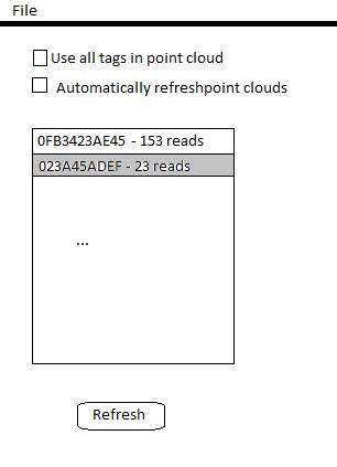
Automatically refresh point clouds every 2 seconds (but have a flag that says whether or not a refresh is necessary to save memory / processing power in the static case)
Meeting with
Matt:
*Tag taped to cardboard box
*Tape a bunch of different tags in 3D
***Make sure they have different IDs
*Cardboard box (with X Y and Z tags) and top five objects
*UPS store on Erwin Road (right next door to Chipotle)
*Don’t forget to take photos
Wednesday 7/21/2010
I decided to put off finishing the point cloud visualization tools until after I leave campus, since I only have 10 days left on campus I want to maximize my time doing things that I can only do on campus like taking experimental data. I had a meeting with Matt yesterday and I decided to bring the roomba back to my apartment for testing. Let me now do a couple of additional measurements before I start running the tests:
*Plane slice laser scan is 6cm above platform base of robot
*Camera is 6.5cm in front of center of laser and about 3.5cm to the right of the robot’s center
*Center of RFID readers are 5cm + 2.54*(4.5) ~ 16.4cm above platform of robot
I’ve applied these changes to the launch file that has the static TF transforms
Trying to get AMCL to initialize at position (0, 0) is proving to be a bit of a challenge
Origin of box array is:
(9.5’ – 2’ + 10”) = 100” to left of starting point (approx -254cm wrt origin)
(25’ – 10”) = 290” in front of starting point (approx 736cm)
Origin of Box array
is: (-254cm, 746cm)
*Robot base is 13cm above ground
Skype meeting with Travis:
*Hide the TV remote inside of the couch (care about placements of the objects)
*Hidden in the bed or in a spot where you can’t see it on the table
*It works where vision doesn’t
*Look into USB cam stuff
Need libhighgui for openCV viewer to work
TODO After I leave:
· Write up tutorial (explain launch files, etc)
· Get visualization tools working
Wednesday 8/4/2010: Official
Apartment Testing Day
NOTE: I decided to start the robot
much closer to the ground truth objects to make ground truth measurement easier
and to minimize amcl error reporting positions
Object Hex
IDs
Box 1: LeftRight -> F00115D Flat-> F001155 UpDown-> F001143
Box 2: LeftRight-> E00114A Flat-> E001148 UpDown-> E001170
Box 3: LeftRight-> E001154 Flat-> F001159 UpDown-> F00115F
Other Objects
· Cup - F00114F
· Bowl - E001144
· Plate - E001150
· Book - E00115E
· TV Remote - E001156
· Scissors - F001145
· Pill Bottle - E001146
· Spoon - E001158
· Perfume/Cologne - F001151
Apartment
Tests Locations
Boxes: LeftRight=>(-24”, 12”), Flat => (-24”, 22”), UpDown => (-14”, 12”)
NOTE: The rest are specified in # of floor blocks (12” x 12” each)
Height 1
· Cologne (1, -3)
· Scissors(-3, -3)
· Cup (-3, 2)
· Medicine Bottle (2, 4)
· Bowl (-3, 4)
· Spoon (-5, 4)
· Remote Control (-6, 3)
· Book (1, 6)
· Plate (-1, 8)
Height 2
· Cologne (2, -3)
· Spoon (3, -3)
· Scissors (2, -4)
· Remote (-2, -2)
· Cup (-3, 2)
· Plate (-3, 4)
· Bowl (-4, 4)
· Book (-11, 8)
· Vitamin Bottle (-11, 9)
Height 3
· Bowl (1, 5)
· Plate (1, 7)
· Scissors (0, 8)
· Cologne (0, 9)
· TV Remote (-2, 8)
· Spoon (-4, 8)
· Cup (-4, 10)
· Vitamin Bottle (-11, 9)
· Book (-11, 8)
Mumma Tests
Locations
Boxes : Updown => (-15”, 14”), LeftRight => (-25”, 14”), Flat: (-25”, 24”)
Height 1
· Spoon (0, -15”)
· Plate(37”, -18”)
· Bowl (-41”, -20”)
· Book(0, -87”)
· Cup (-122”, 22”)
· Medicine Bottle (-122”, 58”)
· Cologne (-113”, -96”)
· Scissors (0, -118”)
· TV Remote under couch (-31”, -118”)
Height 2
· Spoon (0, -15”)
· Plate (37”, -18”)
· Bowl (-41”, -20”)
· Book (0, -53”)
· Medicine Bottle (0, -71”)
· Cup (18”, -71”)
· Cologne (-17”, -71”)
· Scissors (0, -86”)
· Remote (0, -120”)