Line Position Detection Using the C-2 Cam and LM1881 Sync Chip
5/4/2010
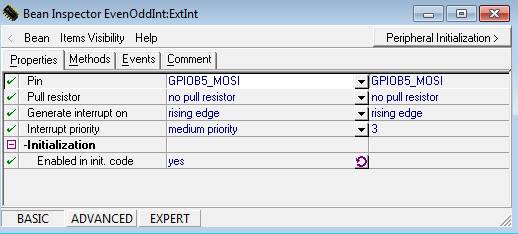
We found that the way to do this was to use a sequence of carefully-timed interrupts based in information from the sync chip. We had an interrupt first that waited for the rising edge of the even-odd signal (about 30hz).
Then once this interrupt fired, we turned on an interrupt that fired on the positive edges of the csync signal from the LM1881 chip. Since there is a blanking interval where there’s lots of junk going on, we counted about 90 of these interrupts to make sure we were actually within a frame before we assumed we were in a scanline
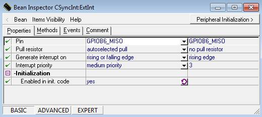
One we counted 90 csync interrupts we disabled the csync interrupt. We disabled it since it happens very rapidly (once every 60 microseconds roughly) and really slows things down; we only want to pay attention to it when we actually need to count to get within a scanline of the frame. This is key for keeping the interrupts from slowing our car down to unreasonable degrees.
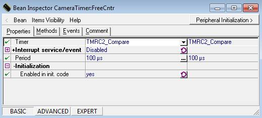
Once we’ve counted around 90 csync interrupts we are confident that we are within a legitimate scanline on the next positive edge of the csync signal. We then have a binary input from the camera itself (quantized to two levels by a comparator) that we can examine to see where the line starts. A free clock cycle tick timer is used in conjunction with an interrupt that looks for a negative edge on the camera comparator input:
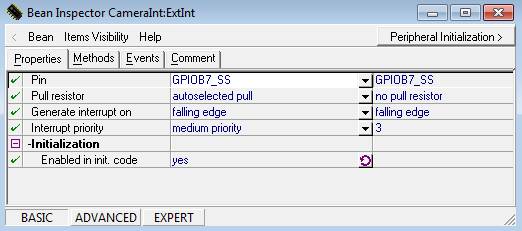
The reason we look for a negative edge is that we want to see when the camera goes from white to black, which is the indication of the start of the line. The time that this interrupt takes to fire tells us how far the line is from the left of the camera, so we can use this information to have us turn.
Currently we have the center of the camera calibrated to take 875 clock ticks. Anything smaller than this means that the line is to the left of the camera and we need to turn left, and anything greater than that means that we need to turn to the right. We have to be careful, though, because if the number is too large, it’s possible that there was no black seen in the threshold; we don’t want to erroneously turn very far to the right in this case. Therefore, we clip the allowable viewing range to be symmetric about 875 clock ticks, but to be limited (in our application it’s 450 clock ticks in each direction). If the camera interrupt takes place outside of this interval we don’t pay attention to where the interrupt actually was; instead we continue to turn in the direction that we previously were turning in. So if the camera loses the line to the left as it’s trying to turn left, it will continue to turn left until the line is found again. This contrasts to the case where we lost the line before and we didn’t clip it to the interval, and the camera never would have seen black (reporting an erroneously large time and making it turn right). We had to experiment to get the proper interval value of 450 since having too small a value meant that the camera would very easily “lose” the line, but having too large of an interval would render this scheme useless and does not prevent overshoot.
5/5/2010-5/6/2010 (late night and early hours of the morning)
With the range set properly, one challenge we encountered with our camera was trying to get the correct angling. At first we angled our camera very sharply, having almost look straight down in front of our car. This presented a problem since the car could not react quickly enough to the changes it sensed in the line and would very easily lose the track after not making the turn fast enough. We then re-positioned the camera with a shallower angle so that it could look farther ahead. However, we overdid it and we noticed that the car take the inside of the track because it was looking too far ahead and thought it had to turn too soon. The result was that the car looked like it was “cutting the corner” of the turn and it would end up more perpendicular than parallel to the track and would then also lose the line. We finally corrected this by angling the camera between these two angles which seemed to work better, and we proceeded to fix the camera in place with glue so that it would not move (it had previously been only secured with electrical tape to allow for adjusting of the angling).
After setting the correct angle, we then proceeded to finally adjust the steering properly. If the camera's interrupt trigger time for viewing the line is within the range of the 875+/-450 clock ticks, we decided to have the turning response linearly related to the distance from the center. A larger distance from the center induces a larger turning response. In trial runs once we were set on the +/-450 range we noticed that we weren't turning hard enough, so we actually “overshot” the turning proportion. The physical limitations of turning the wheels corresponded to steering duty cycle fractions of about 0.144 maximum and 0.108 minimum (setting above the maximum or below the minimum had no ill effects, the wheels would just not turn any more) with a center of about 0.126 as all measured during the slalom portion of the lab. To get the correct steering response we wanted, we set the turning duty cycle to be linear from 0.098 to 0.154 based on the black line's calculated distance from center. This way, the car would turn harder when it the line would vary from the calculated center distance.
When we were competing in the race we changed the response from linear to cubic on the interval [-1, 1], so that it would match up in the extreme cases but it wouldn’t turn as much when it was close. This prevented intense wiggling on the straightaways that would have resulted from using linear proportions, but allowed it to try to match the turns. It worked well for the straightaways and some of the turns except for the portion of the track in “C” where there are many turns close to each other since this would cause a lot of wobbling and the car would then go off the track.